Project ScratchDuinoRobotKit blackline
From scratchduino
(Difference between revisions)
| Line 28: | Line 28: | ||
||[https://youtu.be/1VJxK9uEw7A Arduino IDE Video] <br> [http://wiki.robbo.ru/wiki/%D0%A4%D0%B0%D0%B9%D0%BB:Black_line_analog1_zigzag.ino Download the sketch] | ||[https://youtu.be/1VJxK9uEw7A Arduino IDE Video] <br> [http://wiki.robbo.ru/wiki/%D0%A4%D0%B0%D0%B9%D0%BB:Black_line_analog1_zigzag.ino Download the sketch] | ||
|- | |- | ||
| − | |colspan=6| <center>'''<font color="red">Algorithm 2 </font>''' The robot uses '''SEVEN (FIVE, in case of USB)''' numerical values of the line sensor — these are values between <br> two extreme values, obtained when the sensor is positioned above the white area and above the black line. <br><br>The readings of the sensor are as follows: </center>'''» 0''' means the position above the white area. Both motors are on and in full swing (255), the left-hand motor is rotating forward, the right-hand motor is rotating backward. The robot turns in place during 0.1 second. <br>'''» 1''' means the position above the white area, closer to the black line. The left-hand motor is on and in full swing (255), rotating forward, while the right-hand motor is off. The robot turns on the fly during 0.1 second. <br>'''» 2''' means the position at the border of the white and black areas, even more closer to the black line. The left-hand motor is on and in full swing (255), rotating forward, while the right-hand motor is at its half (120), rotating forward, too. The robot goes ahead and turns a bit, on the fly, during 0.1 second. <br>'''» 3''' means the position at the border of the white and black areas, already above the black line. The left-hand and the right-hand motors are on and in full swing (255), both rotating forward. The robot goes ahead during 0.1 second. <br>» The rest of the values ('''4''', '''5''', and '''6''') are mirroring the '''0''', '''1''', and '''2''' options, respectively. <center><br> The trajectory the robot follows is a smooth curve with long tangent sections, so the robot can travel all along without slowing down. <br> [[File:Line.png]]<br></center> | + | |colspan=6| <center>'''<font color="red">Algorithm 2 </font>''' The robot uses '''SEVEN (FIVE, in case of USB)''' numerical values of the line sensor — these are values between <br> two extreme values, obtained when the sensor is positioned above the white area and above the black line. <br><br>The readings of the sensor are as follows: </center>'''» 0''' means the position above the white area. Both motors are on and in full swing (255), the left-hand motor is rotating forward, the right-hand motor is rotating backward. The robot turns in place during 0.1 second. <br>'''» 1''' means the position above the white area, closer to the black line. The left-hand motor is on and in full swing (255), rotating forward, while the right-hand motor is off. The robot turns on the fly during 0.1 second. <br>'''» 2''' means the position at the border of the white and black areas, even more closer to the black line. The left-hand motor is on and in full swing (255), rotating forward, while the right-hand motor is at its half (120), rotating forward, too. The robot goes ahead and turns a bit, on the fly, during 0.1 second. <br>'''» 3''' means the position at the border of the white and black areas, already above the black line. The left-hand and the right-hand motors are on and in full swing (255), both rotating forward. The robot goes ahead during 0.1 second. <br>'''»''' The rest of the values ('''4''', '''5''', and '''6''') are mirroring the '''0''', '''1''', and '''2''' options, respectively. <center><br> The trajectory the robot follows is a smooth curve with long tangent sections, so the robot can travel all along without slowing down. <br> [[File:Line.png]]<br></center> |
|- | |- | ||
|25–26 seconds | |25–26 seconds | ||
Revision as of 15:39, 25 June 2018
Name of author (s)
Description of the ROBBO Scratch project
| Trip time | Sketch | Power supply | ROBBO Scratch | Trip time | Arduino IDE |
|---|---|---|---|---|---|
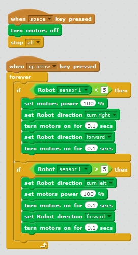
| two extreme values, obtained when the sensor is positioned above the white area and above the black line. If the sensor shows a value greater than the average, then the robot turns to the left during 0.1 second and goes forward during 0.1 second. If the sensor shows a value less than the average, then the robot turns to the right during 0.1 second and goes forward during 0.1 second. The trajectory the robot follows is a zigzag.  | |||||
| 38 seconds | 
|
USB | ROBBO Scratch Video Download the sketch |
30 seconds | To turn the robot on and off, two touch sensors are used: analogRead(A3) – right-hand rear sensor — ON, analogRead(A1) — left-hand rear sensor — OFF Download the sketch |
| 13 seconds | The high speed causes numerous errors. At a high speed, the robot misses the turns in half the cases. |
Battery 7.4V | ROBBO Scratch Video Download the sketch |
11 seconds | Arduino IDE Video Download the sketch |
| two extreme values, obtained when the sensor is positioned above the white area and above the black line. The readings of the sensor are as follows: » 1 means the position above the white area, closer to the black line. The left-hand motor is on and in full swing (255), rotating forward, while the right-hand motor is off. The robot turns on the fly during 0.1 second. » 2 means the position at the border of the white and black areas, even more closer to the black line. The left-hand motor is on and in full swing (255), rotating forward, while the right-hand motor is at its half (120), rotating forward, too. The robot goes ahead and turns a bit, on the fly, during 0.1 second. » 3 means the position at the border of the white and black areas, already above the black line. The left-hand and the right-hand motors are on and in full swing (255), both rotating forward. The robot goes ahead during 0.1 second. » The rest of the values (4, 5, and 6) are mirroring the 0, 1, and 2 options, respectively. The trajectory the robot follows is a smooth curve with long tangent sections, so the robot can travel all along without slowing down.  | |||||
| 25–26 seconds | ROBBO Scratch хуже, чем Arduino IDE обрабатывает время движения, поэтому количество диапазонов мы сократили до 5 и упростили движение моторов. Они все время двигаются вперед с разной мощностью |
USB | Download the sketch | 18 seconds | Arduino IDE Video Download the sketch |
| 12 seconds | At a high speed, the robot misses the turn in 4 of 5 cases. |
Battery 7.4V | It is important to modify the sketch coded for USB, because at a high speed, the in-between values of the sensor cannot be handled. Объединяем все промежуточные значения Download the sketch |
9.5 seconds | It is important to immediately modify the sketch, coded for a 5V power supply (USB). Заменить время движения робота в поворотах со 100 до 10 milliseconds. А время движения прямо увеличить до 200 milliseconds. It is necessary because at a high speed, the robot rushes too fast along the path section where the values of the sensors are changing. |
| is positioned above the white area and above the black line. The trajectory the robot follows is a line with long straight sections, and the robot can travel all along without slowing down.  | |||||
| XX seconds | |||||
| XX seconds | 8.5 seconds (track record!) | Arduino IDE Video Download the sketch | |||
Описание проезда по чёрной линии с ДВУМЯ датчиками
Сложную трассу с перекрестками, ответвлениями, "зебрами" и инверсными участками с одним датчиком проехать невозможно. При подключении двух датчиков требуется использовани специальных алгоритмов, которые автоматизируют движение робота.
| Trip time | Sketch | Power supply | ROBBO Scratch | Trip time | Arduino IDE |
|---|---|---|---|---|---|
 | |||||
| XX seconds | 
|
USB | При питании от USB робот останавливается на повороте, т.к. оба датчика оказываются на черной линии Download the sketch |
XX seconds |
analog0 = analogRead(A0); // Got a value from the sensor analog1 |
| 10 seconds | 7.4 V | When extra powered from the battery, the robot cuts the sharp turning off, because at a speed, the sensors cannot be above the black line both at the same time ROBBO Scratch Video Download the sketch |
XX seconds | Arduino IDE Video. If the battery is run down, the robot stops at the turn. Download the sketch - sensor readings Download the sketch - простой релейный регулятор + ON/OFF by touch sensors | |
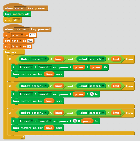
| E = S1 – S2. To obtain the value of controlling action U, we multiply this value by a chosen ratio kp: U = kp⋅E. U is the momentum that we have to add to one motor and extract from other motor. Thus, the robot will control its position itself — that is, for turning or taxing to the required direction. | |||||
| XX seconds. | USB | ROBBO Scratch Video |
XX seconds | Download the sketch | |
| 7.4 V | ROBBO Scratch Video Download the sketch |
XX seconds | Arduino IDE Video Download the sketch | ||
| <center>Algorithm 6 Пропорционально-дифференциальный регулятор | |||||
| USB | |||||
| 7.4 V | ROBBO Scratch Video Download the sketch |
XX seconds | Arduino IDE Video Download the sketch | ||
| | |||||
| XX seconds | USB | ||||
| XX seconds | Battery 7.4 V | ROBBO Scratch Video Download the sketch |
XX seconds | Arduino IDE Video Download the sketch | |